Motor phase loss protection and complementary operation device
Power-dragging equipment has been widely used in power systems, and is mainly based on small three-phase asynchronous motors, such as circuit breaker energy storage motor, main transformer cooling motor, disconnector operating motor, transmission motor and servo motor in power plants. Wait. In the field operation, the damage rate of these motors is relatively high. The reasons are: (1) motor phase loss operation; (2) long-term overload operation; (3) unfavorable operation and maintenance; (4) poor performance of the motor itself. After analysis: The power supply and motor control loop is not reliable, causing the motor to run in phase loss is the main reason for motor damage. Therefore, the lack of phase protection of the motor has been used in a considerable range. At the same time, the backup power supply mode provided by the dual power supply loop is also used in some important occasions to effectively prevent the motor from operating due to a phase power failure and ensure that the motor is in operation. Continue to run under standby power. However, in some motor control loops there are many factors that cause phase loss, such as broken fuses, broken control loops, poor contactor contacts. For these reasons, the lack of phase protection of the motor can act reliably, cutting off the other two-phase power supply to stop the motor and prevent the motor from being damaged. In general, the lack of phase protection of the motor can protect the motor, but in some special occasions, the stall of the motor will endanger the safe operation of the system. If the energy-storage motor of the circuit breaker is stopped, the circuit breaker will lose the switching energy, and the accident will be Circuit breaker refused to move. Especially in an unattended substation, if the energy storage motor fails to be handled immediately after a phase-to-phase stop, the circuit breaker will be locked for a long time, which may cause the accident scope to expand and even cause the system to collapse. This article describes the motor phase loss protection and complementary re-operation device, proposes a method to use a sound phase voltage, according to the principle of magnetic coupling out of the lack of phase voltage to make the motor continue to run the motor, has an important role in improving the safe operation of the power system .
1 Basic Principles There are two options for implementing phase compensation and re-operation after missing the motor phase: (1) Automatically put a backup power supply at the input of the motor; (2) Automatically coupling the missing phase voltage into the motor by a healthy 2-phase voltage. The first solution is easier to implement, but it requires two-way power supply. At the same time, the lack of phase caused by the motor control loop can not be put into work properly, so it has certain limitations; the second solution requires a split-phase device, but does not need to double Road power supply, and can be applied to a variety of reasons caused by the lack of phase failure, the principle shown in Figure 1.
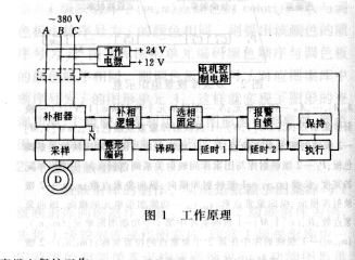
1.1 Working Power Supply The working power supply adopts a three-phase rectifier capacitor voltage divider and a stable power supply. It is simple, reliable, and economical. Due to the use of three-phase rectification, the working power will not disappear after the phase loss and will continue to work under the 2-phase power supply. The power output is +24V and +12V. +24V is used to perform the relay drive and +12V is used for the logic circuit.
1.2 Phase-to-phase protection This part consists of six units: sampling, shaping coding, decoding, delay, alarm self-locking, and execution self-holding.
1.2.1 Phase loss protection of the sampling unit The unbalanced voltage sampling principle is usually used. Voltage sampling is easier to implement. However, the lack of phase protection by the voltage sampling principle does not reflect the disconnection of the winding inside the motor. At the same time, since most of the motor is still running after the phase is missing, the missing phase winding will continue to cut the magnetic field to generate the induced potential, which is substantially the same phase as the missing power phase and has an amplitude of about 80% Ue. This makes the unbalanced voltage of the three phases unobvious. Therefore, the sensitivity of the phase loss protection composed of the voltage sampling principle is low, and it is likely to cause refusal. To obtain a more reliable phase loss protection, the current sampling principle is used. Although the current sampling is complex and requires a current transformer, it is sensitive to the missing phase potential and can reflect the internal disconnection of the motor. Therefore, it has high sensitivity and is not susceptible to misoperation.
1.2.2 Shaped coding unit After the three-phase sampling and output of the current transformer, they are respectively sent to a triode shaping circuit through rectification, resistance limiting and capacitance filtering, and three DC potentials are shaped and output. If a certain potential is a high level "1", it means that the corresponding phase does not have a phase, low level "0" means that the phase is not normal; if all three potentials are high "1", it means that the motor is normal. Stop; if all three potentials are low "0", it means the motor is running normally.
1.2.3 The decoding unit sends the shaped potential to a decoding unit composed of an integrated circuit, and the decoding unit interprets the missing phase according to the input potential level, as shown in FIG. 2 . a, b, c are decoder input terminals, and Y1, Y2, and Y3 are decoders.
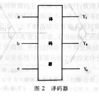
Output. The Y1 high level indicates that the phase loss phase is other than the A phase, the Y2 high level indicates the absence of the B phase, and the Y3 high level indicates the absence of the C phase. The true value of the decoder is shown in Table 1.

1.2.5 Alarm self-locking unit This unit uses an integrated circuit bistable flip-flop, and the trigger potential is delayed by 1 from the delay unit. That is, regardless of whether the complement is successful or not, it will send out the missing phase alarm information, and at the same time show the lack of Different from each other.
1.2.6 Execution of self-protection unit Since the thyristor has a good self-maintaining performance, the self-protected component is implemented with a thyristor-driven high internal resistance small-seal relay. The use of high internal resistance relays reduces power consumption and simplifies the operation of the power supply.
1.3 Auto-compensation part This part is composed of 3 units of fixed phase selection, complementary logic, and phase changer, as shown in Figure 3.
1.3.1 Phase-selection Fixed-phase unit The phase-selection unit selects the phase-to-phase phase difference according to the output of delay 1 after decoding, and sends it to the phase-adding logic unit, and fixes the output result of delay 1 until the entire device returns.
1.3.2 Compensating Logic Unit This unit performs logic judgment based on the fault phase output from the phase selection unit, and concludes that the phase of the sound phase voltage of the phase compensation device should be different from the fault phase that should be disconnected. The operation of the auto-complementary part is as follows: If the motor lacks the A-phase voltage, the contact J1 from the phase-selective fixed unit is closed, the complementary-phase outlet relay Ja acts, and the normally closed contact Ja-5 disconnects the faulted A-phase, preventing Short circuit or overload occurs after the phase-change power supply is put into the fault phase. The normally closed contacts Ja-1, Ja-4 respectively block the relays Jc, Jb, preventing any two relays from acting at the same time and causing a short circuit.
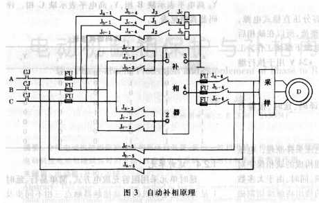
At this time, the sound voltages of phase B and phase C are input to the phase inverter through the normally open contacts Ja-2 and Ja-3. The output voltage of the phase inverter is added to the phase A of the motor through the normally open contact Ja-6. Completion of the complementary process. The closing of the contact J2 indicates the absence of the B phase voltage, the closing of the contact J3 indicates the absence of the C phase voltage, and the complementary process is the same as above.
1.3.3 Phase-compensation unit The phase compensation adopts the principle of magnetic coupling, and a sound 2-phase power supply couples the missing phase voltage by means of the power neutral line. The principle of wiring is shown in Figure 4.
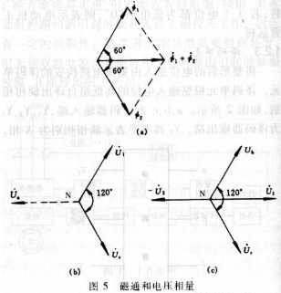
The phase changer consists of two iron cores with completely independent magnetic circuits and the same size, forming a special transformer. The windings L1, L2, and L3 have the same number of turns. In the same direction, L3 crosses 2 cores. The magnetic flux generated by L1 is Φ1, the magnetic flux generated by L2 is Φ2, and the magnetic flux passing through winding L3 is Φ1+Φ2. If the amplitudes of the input voltages at the l terminal and the 2 terminal of the phase inverter are the same and the phases are 120° apart, then the fluxes Ф1 and Ф2 generated by L1 and L2 have the same amplitude and a phase difference of 120°. Therefore, the resultant flux of Ф1+Ф2 should be the vector sum of Φl and Φ2, as shown in Figure 5(a). Assuming that the motor has a phase loss, the phase loss phase is A phase, and the voltage vector diagram is shown in Figure 5(b).
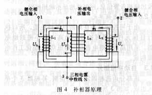
As shown in Figure 4, because the L3 winding and L1, L2 winding reverse polarity output, so the phase of the output voltage of the 4 terminal and U3 is -U3, the vector diagram shown in Figure 5 (c), can be obtained - U3 has the same amplitude and phase as the missing phase voltage Ua. - U3, Ub, Uc equal amplitude, phase difference of 120 ° constitute a three-phase symmetrical power supply, can continue to normal motor operation.
1.3.4 Output Capacity of the Phase Comparator The size of the core, the number of turns of the winding and the thickness of the wire diameter are related to the load of the phase changer, that is, the output capacity of the phase changer is related to the power of the motor and should be based on the size of the motor power. Select core and wire diameter.
Because of the magnetic coupling principle of the phase changer, the resultant magnetic flux in L3 is the vector sum of magnetic fluxes generated by L1 and L2. Therefore, the combined magnetic flux is the same as the magnetic flux in a single core, so the working efficiency of a single core is 50%. If a three-phase motor with a power of 1.5 kW is used for phase compensation and 0.5 kW is to be added to the 1/3 power it lacks, then the ideal phaser should consist of two cores with a capacity of 0.5 kW. Considering the loss of the core and the overload capability of the phaser, the capacity of a single core should be appropriately increased.
2 Field application The actual operation of the device on the circuit breaker energy storage motor shows that the automatic phase compensation system can correctly cooperate with the phase loss protection and can work correctly and reliably in all kinds of phase loss situations. The device can not only be widely used in the power system, but also can be widely used in the civil industry.
Firstly, compared to other colors, black is widely recognized as a popular color. No matter where black is used, today we will talk about our company's black Electric Bicycles. Whether it is mountain electric bicycles or City Electric Bicycles, black can reflect the calm, introverted, and mysterious temperament of cyclists. Our company's independently developed MC01, MC02, and LiXA Mountain Electric Bike Frames all use black as the main color tone. The Mountain Ebike itself is a preferred model for outdoor mountain cycling enthusiasts, and the black electric bike frame can better showcase the charm and unique temperament of outdoor cycling. Imagine what a cool and handsome thing it would be for you to ride a black electric power assisted bicycle and fly through the mountains. The urban Electric Bicycle series requires different riders to choose from due to the environmental conditions they ride. Some prefer low-key black, some prefer white, and some prefer highly personalized colors such as red, yellow, blue, purple, or more distinctive colors. In short, regardless of which color you prefer, we can customize your electric powered bicycle for you.
Electric Bicycle,Rental Bike,Rental Bike Near Me
Ejoysport Technology (SuZhou)Co.,LTD , https://www.yqejoysport.com