[Meter's Latest Patent] A Passive Remote Intelligent Water Meter
2024-09-17 14:03:30
[Chinese instrument network meter patent] creative limit, instrumentation invention. Today, we introduced a national invention-issued patent - a passive remote intelligent water meter. The patent was applied for by Suzhou Junren Instrument Technology Co., Ltd. and was authorized to be announced on January 11, 2016.
Description of the Invention The present invention discloses a water meter, belonging to the category of a flow meter, and in particular to a passive remote water meter.
Background of the Invention A water meter is a commonly used meter for measuring water consumption. Since the meter reading of the tap water meter in most residents' homes is still an artificially estimated method, the meter reading has not yet been completed and most residents are inconvenienced. In order to solve this problem, there has been an addition of a remote transmission water meter (also called a data transmission type water meter, hereinafter referred to as an electronic water meter) on the market, and it has been used in some areas. This kind of electronic water meter can realize the function of not reading into the user's home, and can copy the water meter data beyond a certain distance. This greatly facilitates the water company and tap water users and basically solves the above-mentioned problems. However, the existing electronic water meter has a great hidden danger at the same time for everyone's convenience. This means that the electronic water meter must use the power supply during the working process. Once the power meter is disconnected, it will not count or store the data. Loss will affect the interests of water companies and users. At present, most electronic water meters use batteries as their system power supply. Although manufacturers have repeatedly stated that batteries can maintain a service life of 7-8 years, no one can tell when the batteries will be discharged at any time. Once the battery is unable to supply power, The electronic water meter will not be able to obtain meter data, which will be a great loss to the water company.
Existing electronic water meters also have low reliability, such as water leakage, resulting in failure of electronic components to work properly and high maintenance costs. The use of batteries cannot fundamentally solve the problem of water meter reading difficulties.
SUMMARY In view of this, the technical problem to be solved by the present invention is to provide a passive remote water meter.
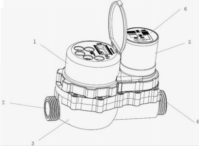
The figure shows the structure of the passive remote intelligent water meter of the present invention The invention provides a passive remote-sensing intelligent water meter, comprising an upper housing, a lower housing, an inlet, a water outlet, an electronically controlled upper cover and an electronically controlled lower cover; wherein, the upper and lower housings are located The internal metering gear set, the impeller box set, the valve ball set and the movement gear set together constitute the counting control system of the water meter; the impeller box set includes the impeller and the impeller shaft, and the impeller sleeve encloses the impeller shaft and is connected to the impeller together with the tip. The filter box is provided at the lower end of the gravity valve cover, and an adjustment screw is also arranged inside the impeller box; the measurement gear set includes a pallet, an upper clamp plate and a lower clamp plate, the plum wheel and the pointer are located inside the upper clamp plate, and the word wheel shaft is connected to the character wheel and Input wheel, the carry axle fixes the carry wheel on the carrying wheel bracket, and the detection wheel is fixed on the detection wheel bracket by the detection wheel bracket shaft; the movement gear wheel set includes the valve control upper clamp plate, the movement gear box and the valve control lower clamp plate. The valve shaft also includes a valve-controlled splint, which is provided with a valve-controlled stainless steel spindle, a valve-opening recharging lever, a valve-controlled recharging valve and a torsion spring, and the gear shaft fixes the valve-controlled recharging valve gear on the valve control. Between the plate and the valve-controlled splint, the valve-controlled cover is located between the valve-controlled splint and the valve-controlled lower splint. The valve shaft is connected with the valve-controlled lower splint, and the spring is fixed on the valve-controlled lower splint by the valve-controlled cover plate. The push rod is set on the valve control plywood plate, and the transmission pinion gear and the transmission gear wheel are respectively fixed on the valve control plywood plate through the shaft. The interior of the movement gear box is also provided with a recharge gear and a metering recharge clutch rod, and the recharge gear passes the plastic rivet. It is fixed inside the movement gear box; the valve ball group includes the valve ball and the valve head. The ball ball end is connected with the valve ball support and the tower spring in turn. The other end of the valve ball passes through the PTFE ring, the valve ball seal ring and the valve end seal in sequence. The ring is connected to the valve end.
In some alternative embodiments, the tip of the impeller bank is located in the center of the impeller box and the impeller hub is nested over the tip. There are three character wheels arranged side by side in the measuring gear set. In the movement gear set, the transmission pinion gear and the transmission gearwheel mesh with each other, and the charging gear is driven through the gears. A PTFE ring, a ball seal, and a valve end seal are placed between the valve ball and the valve head in the ball valve group. When the water meter is recharged and the valve is opened, the user shall prepay the water fee first, and then send a signal to the electronic control device to recharge the water meter through remote control. After the recharge is completed, the electronic control device drives the counting control system to open the valve in reverse and pre-tensions the spring. , After the valve is opened, the user can use water normally. When the water meter is working, it flows into the impeller box group from the inlet to push the impeller box group to rotate, the impeller box group drives the measuring gear group to rotate, the measuring gear group drives the character wheel to rotate, the character wheel turns and displays the count as decreasing mode, when all character wheels When the counts are all zero, the push rod is actuated by the spring force to open the valve to recharge the clutch lever, and the valve recharging valve gear loses the friction of the opening lever retraction lever, releases the spring preload, and drives the valve shaft to close the valve.
The invention has the advantages of simple structure, novel design, simple control, good practicability and high market value, and is convenient for popularization and application.
For more information, please download the full specification of the patent.
More information on the latest technology of meter technology patents, please continue to pay attention to [instrument patents]
Description of the Invention The present invention discloses a water meter, belonging to the category of a flow meter, and in particular to a passive remote water meter.
Background of the Invention A water meter is a commonly used meter for measuring water consumption. Since the meter reading of the tap water meter in most residents' homes is still an artificially estimated method, the meter reading has not yet been completed and most residents are inconvenienced. In order to solve this problem, there has been an addition of a remote transmission water meter (also called a data transmission type water meter, hereinafter referred to as an electronic water meter) on the market, and it has been used in some areas. This kind of electronic water meter can realize the function of not reading into the user's home, and can copy the water meter data beyond a certain distance. This greatly facilitates the water company and tap water users and basically solves the above-mentioned problems. However, the existing electronic water meter has a great hidden danger at the same time for everyone's convenience. This means that the electronic water meter must use the power supply during the working process. Once the power meter is disconnected, it will not count or store the data. Loss will affect the interests of water companies and users. At present, most electronic water meters use batteries as their system power supply. Although manufacturers have repeatedly stated that batteries can maintain a service life of 7-8 years, no one can tell when the batteries will be discharged at any time. Once the battery is unable to supply power, The electronic water meter will not be able to obtain meter data, which will be a great loss to the water company.
Existing electronic water meters also have low reliability, such as water leakage, resulting in failure of electronic components to work properly and high maintenance costs. The use of batteries cannot fundamentally solve the problem of water meter reading difficulties.
SUMMARY In view of this, the technical problem to be solved by the present invention is to provide a passive remote water meter.
The figure shows the structure of the passive remote intelligent water meter of the present invention
In some alternative embodiments, the tip of the impeller bank is located in the center of the impeller box and the impeller hub is nested over the tip. There are three character wheels arranged side by side in the measuring gear set. In the movement gear set, the transmission pinion gear and the transmission gearwheel mesh with each other, and the charging gear is driven through the gears. A PTFE ring, a ball seal, and a valve end seal are placed between the valve ball and the valve head in the ball valve group. When the water meter is recharged and the valve is opened, the user shall prepay the water fee first, and then send a signal to the electronic control device to recharge the water meter through remote control. After the recharge is completed, the electronic control device drives the counting control system to open the valve in reverse and pre-tensions the spring. , After the valve is opened, the user can use water normally. When the water meter is working, it flows into the impeller box group from the inlet to push the impeller box group to rotate, the impeller box group drives the measuring gear group to rotate, the measuring gear group drives the character wheel to rotate, the character wheel turns and displays the count as decreasing mode, when all character wheels When the counts are all zero, the push rod is actuated by the spring force to open the valve to recharge the clutch lever, and the valve recharging valve gear loses the friction of the opening lever retraction lever, releases the spring preload, and drives the valve shaft to close the valve.
The invention has the advantages of simple structure, novel design, simple control, good practicability and high market value, and is convenient for popularization and application.
For more information, please download the full specification of the patent.
More information on the latest technology of meter technology patents, please continue to pay attention to [instrument patents]
Neutral Silicone Adhesive For Interior Decoration
Neutral Silicone Adhesive For Interior Decoration,Anti-Mildew Silicone Sealant For Kitchen,Bathroom Super Adhesive,Waterproof One Component Silicone Glass Sealant
Shandong Tongchuang Rubber Industry Co.,Ltd. , https://www.tcadhesive.com